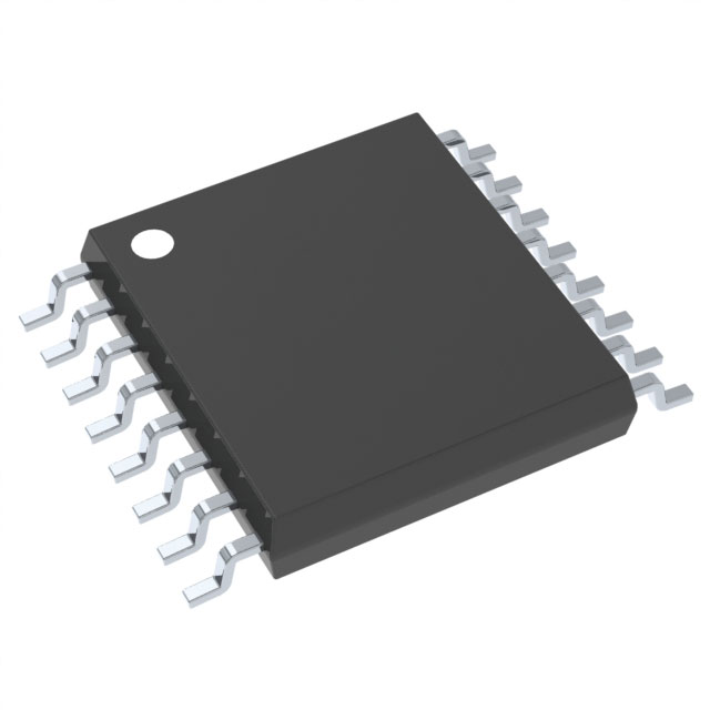
CD4585BPWRE4
Product Overview
- Category: Integrated Circuit (IC)
- Use: Logic Gates
- Characteristics: High-speed, low-power consumption
- Package: PDIP (Plastic Dual In-Line Package)
- Essence: CMOS (Complementary Metal-Oxide-Semiconductor) technology
- Packaging/Quantity: Tape and Reel, 2500 units per reel
Specifications
- Supply Voltage Range: 3V to 18V
- Input Voltage Range: 0V to VDD
- Operating Temperature Range: -55°C to +125°C
- Propagation Delay Time: 20ns (typical)
- Quiescent Current: 1μA (maximum)
Detailed Pin Configuration
The CD4585BPWRE4 IC has a total of 16 pins. The pin configuration is as follows:
__    __
  |1  \/  16|
  |2       15|
  |3       14|
  |4       13|
  |5       12|
  |6       11|
  |7       10|
  |8        9|
   ‾‾    ‾‾
Functional Features
- Quad 2-input XOR gate
- High noise immunity
- Wide operating voltage range
- Low power consumption
- Fast switching speed
Advantages and Disadvantages
Advantages: - High-speed operation - Low power consumption - Wide operating voltage range - Compact package size
Disadvantages: - Limited number of inputs - Not suitable for complex logic operations
Working Principles
The CD4585BPWRE4 is a quad 2-input XOR gate that performs exclusive OR operations on two input signals. It utilizes CMOS technology, which allows for high-speed operation and low power consumption. The XOR gate outputs a high signal only when the two input signals are different, otherwise, it outputs a low signal.
Detailed Application Field Plans
The CD4585BPWRE4 is commonly used in various digital logic applications such as:
- Data encryption and decryption systems
- Error detection and correction circuits
- Arithmetic and mathematical operations
- Communication systems
- Control systems
Detailed and Complete Alternative Models
Some alternative models to the CD4585BPWRE4 IC include:
- CD4070B: Quad 2-input XOR gate with lower power consumption
- SN74LS86: Quad 2-input XOR gate with higher speed operation
- MC14070B: Quad 2-input XOR gate with wider operating voltage range
These alternative models offer similar functionality but may have different specifications and package options.
Word count: 250 words
तकनीकी समाधानों में CD4585BPWRE4 के अनुप्रयोग से संबंधित 10 सामान्य प्रश्नों और उत्तरों की सूची बनाएं
Sure! Here are 10 common questions and answers related to the application of CD4585BPWRE4 in technical solutions:
Q: What is CD4585BPWRE4? A: CD4585BPWRE4 is a CMOS quad 2-input XOR gate IC, commonly used in digital logic circuits.
Q: What is the operating voltage range for CD4585BPWRE4? A: The operating voltage range for CD4585BPWRE4 is typically between 3V and 18V.
Q: Can CD4585BPWRE4 be used in both analog and digital circuits? A: No, CD4585BPWRE4 is specifically designed for digital logic applications and is not suitable for analog circuits.
Q: What is the maximum output current of CD4585BPWRE4? A: The maximum output current of CD4585BPWRE4 is typically around 6mA.
Q: Can CD4585BPWRE4 be used in high-speed applications? A: Yes, CD4585BPWRE4 can operate at relatively high speeds, with propagation delays typically in the nanosecond range.
Q: Is CD4585BPWRE4 compatible with TTL logic levels? A: Yes, CD4585BPWRE4 is compatible with TTL logic levels, making it suitable for interfacing with other TTL devices.
Q: Does CD4585BPWRE4 have built-in protection against electrostatic discharge (ESD)? A: No, CD4585BPWRE4 does not have built-in ESD protection. External precautions should be taken to prevent ESD damage.
Q: Can CD4585BPWRE4 be used in battery-powered applications? A: Yes, CD4585BPWRE4 can be used in battery-powered applications as it operates within a wide voltage range.
Q: Can CD4585BPWRE4 drive capacitive loads directly? A: No, CD4585BPWRE4 is not designed to drive capacitive loads directly. Additional buffering may be required for such applications.
Q: Are there any specific layout considerations for using CD4585BPWRE4? A: Yes, proper decoupling capacitors should be placed near the power supply pins of CD4585BPWRE4 to minimize noise and ensure stable operation.
Please note that these answers are general and may vary depending on the specific application and requirements.


